

How To Draw A Plane In Solidworks
In this tutorial, we explain how to create four different reference planes in SOLIDWORKS :
- Starting time Planes
- Angle Planes
- Mid Planes
- Cylindrical Surface Planes
Offset Planes
The most mutual blazon of reference plane is an offset plane . To create an offset airplane, select the Reference Geometry drop down on the CommandManager and choose the Plane option.

Once the option to create a plane is open, select a confront or another plane and gear up a distance for the outset. (Figure 1 & 2) There is also the option to create multiple planes when making an kickoff plane (Figure three). When creating multiple planes this way, all of the planes created will accept the same offset from each other.
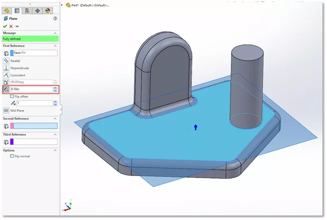
(Figure 1)
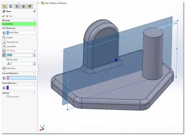
(Figure 2)
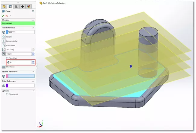
(Figure 3)
Angle Planes
To create an angle plane, you lot'll need a face and an axis line to angle nearly.
The centrality line can exist a model edge or a sketch line. (Figure 4) Past default, the angle of the new plane will exist perpendicular to the selected face/airplane only you can alter the angle at which the plane is first from the selected face.
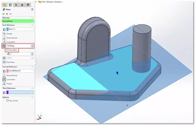
(Figure four)
Multiple angle planes can be created at the same time; each existence starting time from the next by the selected angle. (Figure 5)
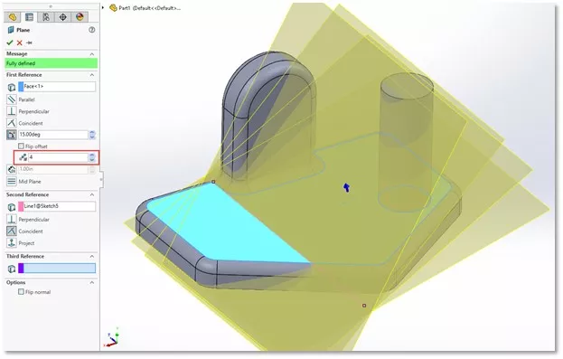
(Figure five)
Mid Planes
When two faces are selected, a mid plane is created by default. The selected faces are not required to be parallel (Figure 6). If they are parallel, the resulting plane will be parallel and halfway between them. If non, the plane will be positioned between the 2 faces. A common apply of this type of airplane would be to create a mirror plane in the center of the part.
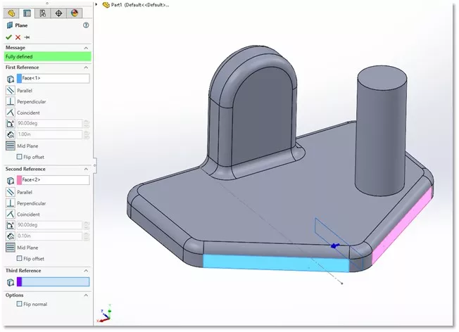
(Figure 6)
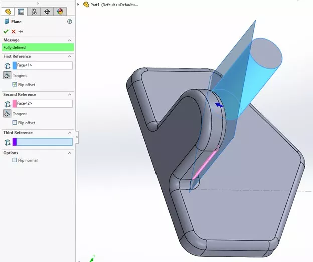
Cylindrical Surface Planes
Planes on cylindrical surfaces can get disruptive because they frequently need more selections in order to finalize the plane. For case, if a cylinder and a plane are selected, the plane will rotate about the cylindrical face as the angle is adjusted. (Figure vii) Or, if multiple cylindrical faces are selected, a plane will be added that is tangent to both.
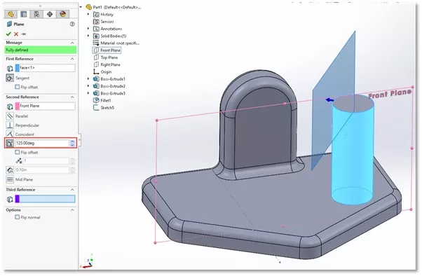
(Figure 7)
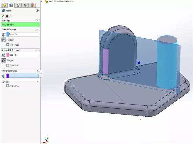
(Figure 8)
(Effigy 9)
In either case, selecting the Flip pick will let you lot set which side of the respective cylinder is used every bit the reference. (Effigy 8 & ix)
I hope you found this commodity helpful. To learn more nearly SOLIDWORKS, cheque out more tips and tricks below.
More SOLIDWORKS Tutorials
Smart Explode Lines in SOLIDWORKS Explained
two Means to Reference a Cross-Section in SOLIDWORKS
Creating and Adding Weld Beads in SOLIDWORKS Models & Drawings
Record a Basic SOLIDWORKS Macro
Favorite SOLIDWORKS Tips from Tech Support
VIEW ALL SOLIDWORKS TUTORIALS

Source: https://www.goengineer.com/blog/creating-reference-planes-in-solidworks
Posted by: cruzsqualoodding1939.blogspot.com
0 Response to "How To Draw A Plane In Solidworks"
Post a Comment